Showing posts with label VR6 Swap. Show all posts

Friday, September 30, 2022

Running the motor again

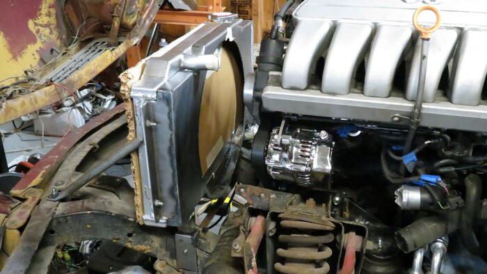
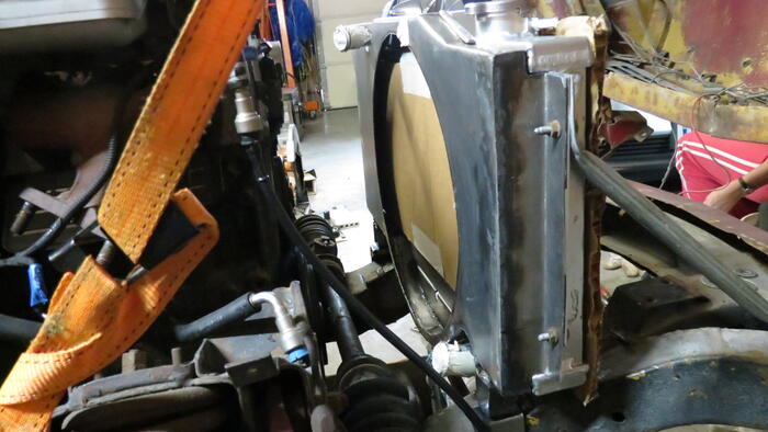
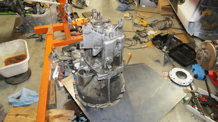
It won't Start! But before I get to that an update on progress. Cooling hoses are connected up enough for testing. Here is a pic I took when it was mostly done.

After the cooling lines were all connected I powered up the electrical system and put the key in and it won't engage the starter. Bad deal. The cluster now says the steering lock is defective and red steering wheel lights up on the dash. That s a new and bad error. We have stripped a ton of wires from the harness but I've checked and all the ones for the steering lock are intact and look good. Using VCDS it surprisingly shows the immobilizer is happy. The steering steering lock is in the unlocked position. The steering lock quit locking on earlier engine starts due to some of the modules I removed.

I'm a bit frustrated with it. Not sure if the steering lock module is now broken, something else is broken, some wire to something else is missing causing it to think it's broken or if the no start is something unrelated. It may be time to remove the IMMO but if the issue is something else that's be kind of a waste and might not fix it. Already spent many hours looking over wiring diagrams and checking things. Fixed a couple wires that were mistakenly removed but so far still no starter action.

I've taken the steering lock apart and checked it to see if it just failed but it appears good. I expect it is likely a wiring problem from us removing gobs of wires or man handling the wires but where? My guess at the moment is either the J393 module or J519 module. Checked over the J393 module connections last night and none of the removed wires appear significant. Did find out that unplugging the J393 module allowed things to power up (T15) and NO steering defective error on the dash (no errors in the text window and and just a few lights). Strange. Oh with J393 plugged in and the steering lock unplugged or the steering wheel module unplugged nothing powers up. Or if the Steering lock is in the locked position (and everything plugged in) nothing powers up (it currently set to the unlocked position.)

Things I changed before the steering lock error went off. I found a ground wire not grounded. However this wire was simply a diode to ground from one of the power leads in the fuse box. Grounding the wire didn't appear to change anything. Recoded the comfort module (J393) back to Auto trans along with the steering wheel electronics back to Auto trans. Then the steering lock error (red steering wheel) went off and the steering lock started actuating again. The engine allowed to start field in VCDS is now showing as Yes.


The cluster still says "depress clutch", odd as I can't find anything that is not coded to auto trans with the exception of the gateway, which I've unchecked the auto trans as that module isn't there. On J519 there is a wire that ran to the P/N switch and looks like may go to the clutch switch on manual trans cars. When grounding that wire (T16g/7) the J519 module sees the P/N switch as activated. With that wire grounded pressing the key all the way in now activates the starter relay. Now I just need a better battery and some fuel and it should run again!

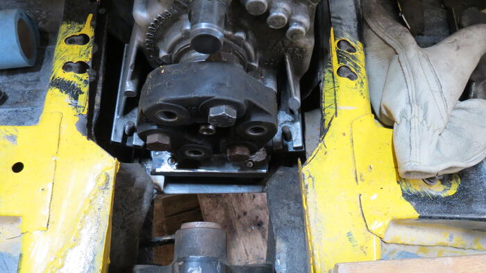
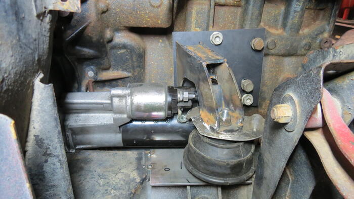
Got a new battery and the car started then died. No new errors. Seemed a bit fuel starved. Ran the pump a bunch of times hoping to get the air out but the engine would fire up, fun a bit and die. The fuel lines were connected the exact same way as the first time. So seemed like it should work. Looking at the fuel pump assembly I noticed a large amount of fuel coming out the extra line, I thought it was just for the 4motion version. The tube I had that would attach there inside the 4motion tank was quite restrictive so I just plugged it (see picture) and the car started and ran just fine. Ran the engine for about 5 min. and shut it down. So success there. The wiring and modules seem happy again.

After looking up new fuel pumps seems the FWD (2wd) version also has this same tube out of the fuel pump? Weird. Will have to research that a bit more.


Below is a picture of the bin holding the wiring and a few electronics boxes we have extracted so far from the wire harness. And that's not even all of it.

Sunday, September 11, 2022

Mounting The Radiator

 Now that we have a fan shroud and radiator it's time to put them in the car. The GT6 and spitfire use different mounting points on the frame.

Since my frame is a GT6 the spitfire mounts aren't there. Also the spitfire puts the radiator into a bracket then mounts it to the frame. Which I also don't have. So decided to make my own mounts.

Wasn't much of a chore to make them. Now the radiator is mounted and I can move on to fitting cooling hoses to the engine.


Saturday, August 20, 2022

Alternator Bracket.....Done


 Been awhile since I took time to work on the car. Most of my Saturdays of late have been dedicated to house projects. And it also got hot so the garage wasn't fun to hang out in. Recently the weather cooled a bit and I thought it was time for a Saturday in the garage.


Last Saturday was spent on the Alternator bracket. I'd cobbled one together for proof of concept but it was too flimsy to hold it while running. 


So basically made a similar bracket but in thicker metal. The final part is 5 pieces welded together. I'd make a paper template from the flimsy bracket then cut it in metal and weld that piece on. 


Looks to have turned out nice and sturdy. One thing done.


Oh one other day I decided to try sitting in the car and see how the steering and pedal position would feel (I've never driven a triumph). I'm also considering changing the steering column to be parallel to the axis of the car instead of angled as it comes from the factory. Also wanted to see what room was there if I used the Passat gas pedal. Anyway I tossed in a two 2x4 chunks stacked to be the seat. After climbing in I tossed out one of the 2x4's as two was too many and my head was too close to the ceiling. That seat won't have much cushion.


Sunday, April 10, 2022

Alternator Bracket, V2, Wiring Thinning

 Since last entry, time has been spent thinning the wiring harness. I purchased a copy of "VCDS" and an interface which is used for coding VW modules. With that I was able to tell most of the modules to not worry about the Auto trans, Electric power steering, tire pressure monitoring, Airbags and bunches of other non essential items. Haven't had time to try and recode the ECU, which is a bit trickier, but with the changes so far we are able to still start the motor without the items previously mentioned attached. With that completed we opened up a lot of the wire harness and started removing unneeded wires. I know wiring is not what some people enjoy but for me it feels like a mix between a puzzle and a treasure hunt. Working on the wiring has been a relaxing activity for the both of us on many evenings.


If memory serves, the past 2 Saturdays were spent making test fit alternator brackets to check clearances. Holding the alternator in position to check clearances and make templates was very difficult so went with the plan to just make something quickly out of scraps and then measure how far off it was to make another better one. Was a good strategy as the first one made didn't work out. no surprise. Originally I mounted the alternator as close to the motor as possible. My first thought was to skip using a tensioner but just swing the alternator out to tension the belt. I'll include a picture of that original setup. But to tension the belt I'd have to slide the alternator up more than pivot it. Decided a tensioner or at the very least an idler pulley would be best. There was no space for the original Passat tensioner and the alternator at the same time. Thought of making my own thing but it looked like the tensioner from the 3.2L 24V VR6 would fit my engine and that tensioner has most of it's structure forward and right of the alternator leaving room for the alternator. Alternator bracket was quickly revised to test placement. In the picture of V2 the tensioner is locked in the nearly full loose position. It will swing to the right (left in the picture) to apply tension to the belt.


Now to see if I can get a belt the right size and make a permanent bracket.


Sunday, March 20, 2022

Car On The Wall


 The weather has improved so there was some time spent in the garage. One thing that needed to be done is to sort out the wiring harness. I pulled the harness, nearly complete, from the donor car. along with most of the computers, switches, fuse boxes etc.. To make it easy to sort out I pinned the wiring up on the wall and then plugged in all the computers and switches. This made it much easier to find the wires I need to keep and what I need to ditch.


While it is there I also plan to use it to test run the motor. With the wiring and computers on the wall I ran the cable for the engine ECU to the car and plugged it in. Also ran some grounding straps to connect the critical items. Put the key in and it lights up and unlocks the steering column and shifter. It looks like every error light still lights though, oh well, I won't be using that cluster anyway so no worries there.


The oil filter and dipstick need to be fitted to the engine before I can even see if it turns over. That's next on the "to do" list.


Monday, December 13, 2021

Engine Repair Complete


Where did November go? Time flies. The engine timing chain, guides, oil pump and high pressure fuel pump cam have all been replaced, Timing covers back on, oil pan cleaned out and resealed. Engine fixed. Now back to customizing.


Sunday, July 11, 2021

Transmission Mounts, Part 2


 Basically I tossed my Transmission mount ideas away from the previous post. After looking at them awhile i decided I hated how the frame would have to be modified. Feel a little bad about the wasted time going down that path but my wife is undeterred. She encourages that we are just on version 2.0.


This time I made a bracket that mounts to the transmission then allows the mounts to be in the middle vertical. Much like most transmissions. This way the frame modification is not all that much. Implemented that solution and while I'd like to move to version 2.1, remaking the brackets for better fit and visual appeal, it works. The engine and transmission are holding the engine in the car.

I used the drive shaft laid in the middle of the frame to help align the trans in the car. Not a lot of wiggle room for the driveshaft. In the process of aligning it I realized how asymmetrical the trans really is. There is a lot more of it on the RH side then the LH side. Unconsciously I had been biasing it to have even gaps on each side and the tail shaft was maybe a half inch to the Left. A little more trimming of things and it all seems good now.

With that done the next goal is to make the motor run in the car. I lightly reattached the intake, fuel rails, high pressure fuel pump and coolant system. Since this is a FWD engine a lot of these things ends up at the back of the engine. Particularly above where the steering shaft enters the body (LH drive). After checking my parts car to see that nothing needed that space, a little more cutting of the body and the engine is in with those attached.

Things that don't fit:
-The coolant outlet is pointing straight at the steering shaft and is close enough that just adding a 90 degree bend to the hose isn't probably going to work. I will likely add a customized cooling tube to move the outlet.
-There isn't room to put the alternator where it was. At least not the factory one.
-The oil filter isn't even close to fitting. An oil filter relocation will need to be done. Sadly oil filter relocation isn't common for this engine.

Tuesday, July 6, 2021

Transmission Mounts, Part 1

 Next up on the to do list is the transmission mounts. Trying to finalize the transmission location it was a good time to pull out a drive shaft (or piece of a drive shaft) and use that to help locate the trans. Of course I spent too much time fiddling trying to get it to the "perfect" location. Which often turns out to not be the perfect location so I wonder why I spend so much time on it :-) Long story short.


Did a bit more clearancing for the transmission
Adjusted the LH motor mount so the intake (where it hits the hood) is level
Created some plates to weld into the frame for the transmission mounts.

The transmission mounts on this trans sit much lower than the triumph. So I have to move the frame mounting around. The mounts are also not symmetrical. Something I had noticed years ago on this style trans. Not a big deal when bolting parts together but fabricating the mounting surface at strange angles requires some care. I made the mounting plates then welded some scrap between them to keep them at the right angles. Then realized I couldn't get that into the frame. So made them bolt together. Will remove that once they are solidly located.

More to do on this.


Sunday, June 20, 2021

Motor Mounts Almost Done

 It seems it has been awhile since I had some good time with the Triumph. Family events, sickness and yard work have taken their share. As much as I want to working on the car every weekend isn't practical. :-) But this weekend was car weekend.

I had mocked up some motor mounts in Cardboard and set about making them into metal. The mount extensions aren't yet tacked into the metal plates. I thought it best to give myself a little thinking time before locking it down. This came after getting the motor all aligned straight, centered and level in the bay. I was about to tack the one side on when I thought I should test fit the hood closing. I did and the intake was hitting the hood. Which reminded me that the best fit wasn't with the motor exactly vertical. Ohhh yah. I shifted the engine over to where it was when I was doing test fitting much earlier and it looks much better. But the trans is hitting on the mount brackets keeping from fine tuning the fit. A job for another day. Anyway...


The RH side arches over the starter then curves forward to the mount. I'm attempting to leave the gap between the motor and the frame open for the exhaust to go through.

The LH side I realized my complicated mock up wasn't needed and I could just go straight across to the engine as there is nothing in the way (Gussets to be added later). The white pipe in the picture is roughly where the steering shaft will be (The pipe is a little low). The mount clears it nicely.

Unfortunately The motor shifted forward when the motor was tilted which can be seen pretty clearly on the LH motor mount shot.


Tuesday, May 18, 2021

Motor Mounts On The Frame

Little late on posting this week as what seemed like should take a few hours took much more. Had a bit of difficulty getting the holes where I wanted them which required re-work. oh well. Got it in now.


Looking at the finished product it doesn't look like much. But the mounts are not just fastened to the thin wall of the frame (about 14 gauge). I drilled a 1 1/4 hole all the way through top and bottom then welded in some pipe, welded in a 3/16 plug in the end of the pipe and drilled that for the motor mount. Then covered all of that with a 1/8 plate (tack welded at the moment). Should give it some strength.


The other tricky bit is that inside of the frame there is some supporting structure for the "A" arms I had to miss. But wanted to be as close to it as possible. Took some massaging of the holes after they were drilled to get it all to work out.


Sunday, May 9, 2021

More Engine And Trans Fitting

Getting the motor and trans to sit inside the engine bay is one thing. Getting them to sit level and not banging on anything is another. This week was spent doing more fine tuning on the location and checking how other things might fit (starter, alternator etc.).


After some time noticing how tight everything is between the suspension towers I went and checked out another swap project. Whoa. There was lots more cutting that I had thought. Made the cutting I had done so far look insignificant. Encouraged by the work of others I started cutting a bit more while still being conservative. Some more trimming and adjusting is required but it's pretty close to where it'll stay. It even fits with the starter on and there looks to be enough room for the exhaust to pass between the block and the frame.

Now that I have the location I have to come up with motor mounts for it. This is a bit of a challenge as I need to leave room for the exhaust and steering. I'd also like to use some mounts that do a good job of cutting NVH (usually requires large mounts). And I have to change up the oil filter/oil cooler combo bit as it won't fit at all.  And need to know what to leave room for. So lots of time planning and not so much fabricating over the last couple days.

It's nice to have it at a good location. Now to get it to stay there :-)


Sunday, May 2, 2021

Engine And Trans Test Fit

Things seem to be going kind of slow this week. But did get a few things done. Got the starter mount hole cut and starter fitted. Welded a stud in one place and a backing nut in another to allow the trans to mount. Need to do some countersinks for a few bolts on the motor but the tool didn't show up in time. For test fitting the few bolts I have are just fine.


Tipped up the motor, put the trans on and tossed it into the car. There are several interference areas that need to be addressed that are not allowing the engine to lower to where I had it before. But with enough cutting and welding just about anything "fits" :-)


Sunday, April 25, 2021

More VR6 RWD Motor Adapter Plate


More work done on the motor adapter plate. Most of the trans to plate holes are now drilled. And the perimeter is roughly cut out. So much easier to handle the smaller plate. Still need to cut the hole for the starter. Then it'll be time to test fit the assembly to the car.


Sunday, April 18, 2021

VW VR6 Motor To BMW E46 Trans Adaption

One problem with the motor I choose was it was in only FWD or AWD cars only. No RWD trans exists. This requires an adapter. I've made a trans adapter before on my EV project. Really didn't want to do that for this project but this is how it turned out.

After what seemed like forever planning and scratching my head for what the best scenario was I ordered a metal plate. It came in friday and work to mate the plate to the motor was started. I've successfully cut the center clearance and the dowel and bolt mounting holes.


Next up mounting the transmission to the plate. This motor has the timing chain on the backside and the timing cover bumps out into the transmission bell housing area. I'm not the first to use this combination and I cut my trans to clear in a similar way. A little more fitting and I can put in the dowel and bolt holes then cut the perimeter out.


Sunday, April 4, 2021

2 Year Anniversary - Introducing the VR6 GT6


 Realized the 2nd year anniversary of my Triumph ownership was this past week. Seems like it would be good to have some a big progress to celebrate. How about some news on the re-engine portion of the project?  The motor is a 3.6L VR6 24 Valve, direct injection, variable valve timing, variable intake, all the goodies. In stock form was rated at 280 hp. Best I can tell the motor weights similar to the GT6 motor, maybe less. It's mounted further back and the Battery will be relocated to the rear. Overall balance should be better than the factory GT6. Time will tell. 

About a year ago I bought the donor car, a 2006 VW Passat, for the engine. Was very anxious to get started on that but forced myself to stick to the body work (which took way too long) to get the back of the car in solid shape before moving on. Then the winter came and progress halted for the winter.

The winter break was a little longer than anticipated as somehow we got the idea we wanted to try sailing in Florida for a vacation trip (since flying has gotten so complicated). Which ended up with us buying a fixer up boat and me doing a lot of projects in the driveway in the cold instead. (How was this better than working in the garage in the cold?). Anyway the boat was finished (well finished enough) and the sailing trip was a complete success. Six great days of sailing and covered about 100 miles. 


Back to the GT6


The first weekend back I made some wooden supports to put the GT6 back on it's skates so it could be moved to the side to make room. Then the donor car was towed into the garage and deconstruction started. This past week I pulled the motor and started fitting it into the GT6. I wasn't sure the engine was going to fit so was quite interested in doing a test fit. Still a lot of fiddling and fitting to do but it looks like it can be made to work (with enough cutting and welding about anything fits. Right?). The engine may even keep it's factory intake.


The hood still doesn't quite close yet but I was out of time to work on it. I think the the hood bracing in sitting on the intake. Will have to do some checking on where it's hitting

when I have some more time.


Beading Floors And Misc

This past  week time was spent trying out a newly purchased beading tool. Being able to bead looked like fun and with so much of the rear fl...